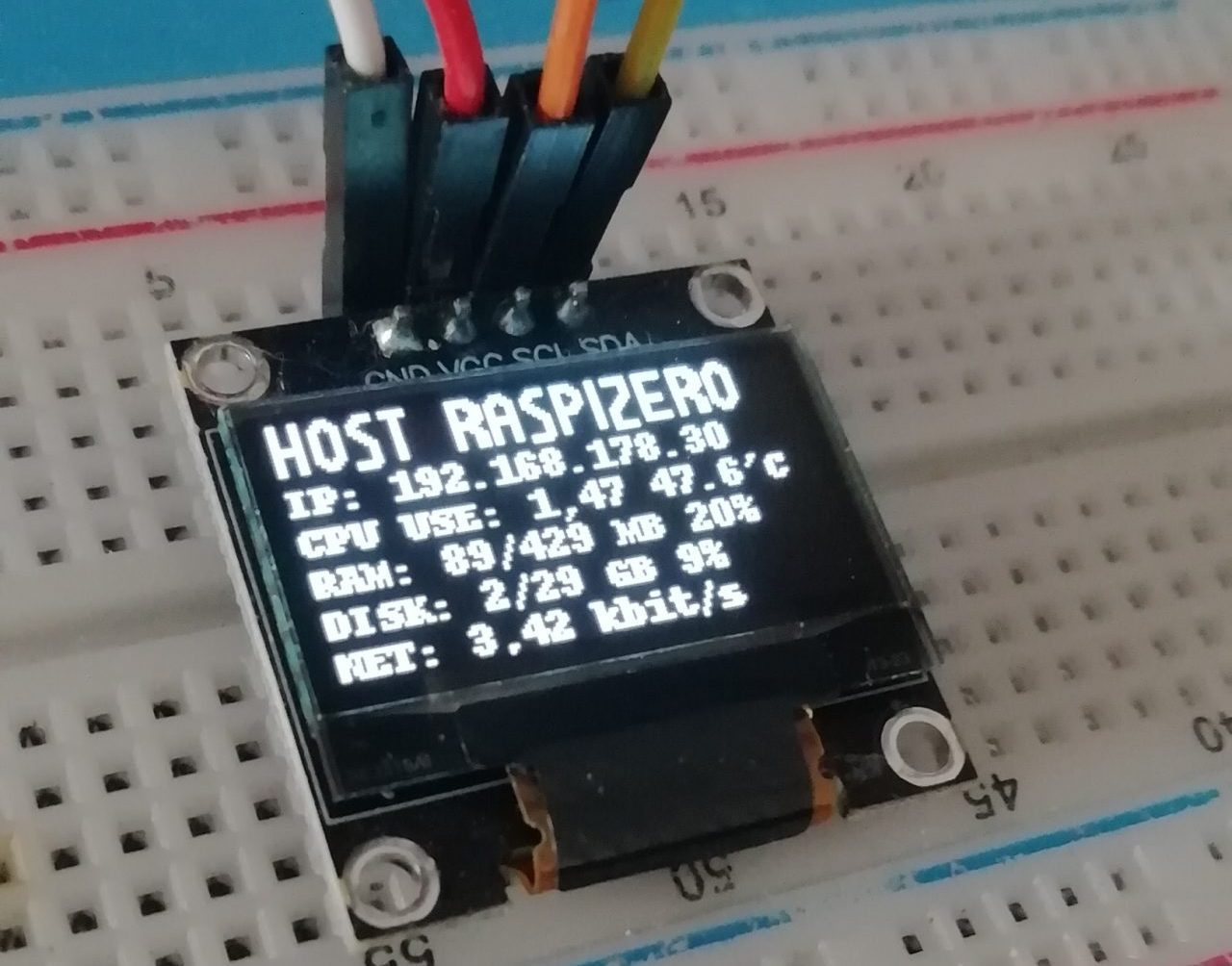
Raspberry Pi Monitoring Display
Hardware-Info und „Stand-by“ Knopf mit Python am 0,96″ I2C OLED
Bauteile:
- Raspberry Pi ZeroW – Pi4 mit Bullseye light OS
- Adafruit 0,96″ I2C OLED Display
- Pushbutton
- Jumperkabel / Breadboard


Terminal öffnen…
Folgende Pakete Zeile für Zeile installieren
sudo apt install -y python3-dev
sudo apt install -y python3-pil
sudo apt install -y python3-pip
sudo apt install -y python3-setuptools
sudo apt install -y python3-rpi.gpio
sudo apt install -y i2c-tools
sudo apt install -y vnstat
sudo apt install -y git
Boot-Config öffnen und bearbeiten
sudo nano /boot/config.txtFür den Shutdown-Button muss Pin 5 verwendet werden. Um auch den Standard-I2C Bus für das Display zur Verfügung zu haben, wird SDA und SCL auf Pin 17 und Pin 27 verlegt (gemappt). Dazu folgende Zeilen am Ende einfügen:
# I2C Bus aktivieren
dtparam=i2c_arm=on

# shutdown/wake-up  function auf pin 5 und pin 6 aktivieren
dtoverlay=gpio-shutdown,active_low=1,gpio_pull=up

# i2c Bus auf Pin 17 (SDA) und 27 (SCL) mappen (standard 5 und 6)
dtoverlay=i2c-gpio,bus=1,i2c_gpio_sda=17,i2c_gpio_scl=27
dtparam=act_led_trigger=default-on
Mit STRG+X die Änderungen speichern, bestätigen und schliessen.
sudo reboot
Beim drücken des Buttons fährt das System nun wie mit „shutdown -r“ sauber in den Bereitschaftsmodus herunter, und kann durch erneutes drücken des Buttons wieder gestartet werden. Oder vom Netz getrennt werden.
Anbindung des Displays mit I2C Adresse checken:
sudo i2cdetect -y 1Mit git die Bibliothek für das Display installieren
sudo git clone https://github.com/adafruit/Adafruit_Python_SSD1306.git

cd Adafruit_Python_SSD1306
sudo python setup.py install
Eine neue leere Python Datei erstellen mit:
sudo nano /home/pi/myoledstats.pyFolgenden Code einfügen und speichern.
#! /usr/bin/python
# coding:utf-8


import time

import Adafruit_SSD1306


from PIL import Image
from PIL import ImageDraw
from PIL import ImageFont

import subprocess

# Raspberry Pi pin configuration:
RST = None     # on the PiOLED this pin isnt used


# 128x64 display with hardware I2C:
disp = Adafruit_SSD1306.SSD1306_128_64(rst=RST)

# Note you can change the I2C address by passing an i2c_address parameter like:
# disp = Adafruit_SSD1306.SSD1306_128_64(rst=RST, i2c_address=0x3C)

# Alternatively you can specify an explicit I2C bus number, for example
# with the 128x32 display you would use:
# disp = Adafruit_SSD1306.SSD1306_128_32(rst=RST, i2c_bus=2)

# Initialize library.
disp.begin()

# Clear display.
disp.clear()
disp.display()

# Create blank image for drawing.
# Make sure to create image with mode '1' for 1-bit color.
width = disp.width
height = disp.height
image = Image.new('1', (width, height))

# Get drawing object to draw on image.
draw = ImageDraw.Draw(image)

# Draw a black filled box to clear the image.
draw.rectangle((0,0,width,height), outline=0, fill=0)

# Draw some shapes.
# First define some constants to allow easy resizing of shapes.
padding = -2
top = padding
bottom = height-padding
# Move left to right keeping track of the current x position for drawing shapes.
x = 0


# Load default font.
font = ImageFont.load_default()

# Alternatively load a TTF font from an absolute path where the fonts lives !
# Some other nice fonts to try: http://www.dafont.com/bitmap.php
fontH1 = ImageFont.truetype('/home/pi/myfonts/m20.ttf',13)
fontH2 = ImageFont.truetype('/home/pi/myfonts/Lexie.ttf',12)
fontH3 = ImageFont.truetype('/home/pi/myfonts/Lexie.ttf',10)
fontH4 = ImageFont.truetype('/home/pi/myfonts/Happyhell.ttf',12)


while True:

    # Draw a black filled box to clear the image.
    draw.rectangle((0,0,width,height), outline=0, fill=0)

    # Shell scripts for system monitoring from here : https://unix.stackexchange.com/questions/119126/command-to-display-memory-usage-disk-usage-and-cpu-load
    cmd = "hostname -a"                                                         # the command to read the value hostname
    HOST = subprocess.check_output(cmd, shell = True )                          #
    cmd = "hostname -I | cut -d\' \' -f1"
    #cmd = "hostname -I |cut -f 2 -d ' '"
    IP = subprocess.check_output(cmd, shell = True )
    #cmd = "top -bn1 | grep load | awk '{printf \"CPU: %.2f%%\", $(NF-2)}'"
    #CPU = subprocess.check_output(cmd, shell = True )
    #cmd = "free -m | awk 'NR==2{printf \"RAM: %s/%s MB %d%%\", $3,$2,$3*100/$2 }'"
    #MemUsage = subprocess.check_output(cmd, shell = True )
    cmd = "df -h | awk '$NF==\"/\"{printf \"DISK: %d/%d GB %s\", $3,$2,$5}'"
    Disk = subprocess.check_output(cmd, shell = True )
    cmd = "vcgencmd measure_temp |cut -f 2 -d '='"
    temp = subprocess.check_output(cmd, shell = True )
    #cmd =  "vnstat -ru 1 --oneline | cut -f7 -d ';'"
    cmd = "vnstat -tr 2 --json | cut -f20 -d \'\"' "
    Rx = subprocess.check_output(cmd, shell = True )
    cmd = "vnstat -tr 2 --json | cut -f34 -d \'\"' "
    Tx = subprocess.check_output(cmd, shell = True )

    # Write lines of text.
    draw.text((x+18, top+2),    str(HOST,'utf-8'),  font=fontH1, fill=255)
    draw.text((x+1, top+19),  "IP: " + str(IP,'utf-8'), font=fontH2, fill=255)
    #draw.text((x+1, top+31),  str(CPU,'utf-8') + " " + str(temp,'utf-8') , font=fontH3, fill=255)
    draw.text((x+95, top+5), str(temp,'utf-8') , font=fontH3, fill=255)
    #draw.text((x, top+36), str(MemUsage,'utf-8'), font=fontH3, fill=255)
    draw.text((x+1, top+32), str(Disk,'utf-8'), font=fontH3, fill=255)
    draw.text((x+1, top+43), "Rx: " + str(Rx,'utf-8'), font=fontH3, fill=255)
    draw.text((x+1, top+54), "Tx: " + str(Tx,'utf-8'), font=fontH3, fill=255)
    #draw.text((x, top+16),    str(MemUsage),  font=font, fill=255)
    #draw.text((x, top+25),    str(Disk),  font=font, fill=255)


    # Display image.
    disp.image(image)
    disp.display()
    time.sleep(.1)
Um das Skript bei jedem Bootvorgang gleich mit zu starten wird in der Datei
sudo nano /etc/rc.localfolgende Zeile hinzugefügt (vor exit0 !)
sudo python3 /home/pi/myoledstats.py &Das „&“ am ende lässt den Prozess im Hintergrund laufen.
Die geänderte Datei mit Strg-X und J speichern.
Keine Kommentare